Friday 25 November 2011

Unwind with sketching

During the trip I managed to take a few pictures of fantastically twisted tree that inspired me to draw during the return bus journey with my sketch book, pencil (no rubber), camera and my legs tucked up to support my book I began to draw. This was drawn in 30 minutes on the bus, so it was a little shaky.


Whilst the knowledge was still fresh in my head I continued on to imagine up a creature that had the influence of the tree. I released during the drawing that the tree did look like muscles and so I formed the way the bark was detailed into looking like the muscle of a human (the humanoid tree took me 35 min on the bus). The other sketches I did at home. 


After the humanoid tree sketches I told myself off and returned to drawing environments. I applied the skills I learnt and tried out bits and pieces of scenery.


Sunday 20 November 2011

Sculpture Park

The Sculpture Park bared unexpected fruit, as it helped me see past my original expectations.

These two pictures were taken, with a flash and without. This taught me a valuable lesson, when in Maya, take note that during the texturing process I shouldn’t add too much shading to the texture because the rendering object will add shape and shadows to it.


While I was walking around I stumbled on fantastic research and inspirational image material. For an example these stone beams are covered in ivy that provides information on colour and the perspective of how the ivy plant is curling around the beams.  


As I continued taking photos I started to realise that there is hidden instance in my imagery. In this image I can see a parrot (dinosaur) head that is near the top left of the tree. The head is slightly browner than the tree, the specific shadows gives the shape and distinguishing facial features.


This photo shows the inside of a rotten log but from another perspective it’s a valley that’s sloped up into some caves. Also I can see a face on the right but more man lizard like.


These types of sculptures were scattered around the park. I can see a giant chicken head, a Cyclops head and my favourite, a ditto (Pokemon).

Thursday 10 November 2011

Nouvic Clock Journey Part 4

Uv Mapping The Jumbled Up Mess


1. I looked at the UV map for the first time by clicking the button at the top right. The uvs / faces of the object is all jumbled up.


To get through the morale crushing first step I used the automatic mapping function. After using it I had to make sure to delete the history because if you move the object the uv’s will jumble. The auto mapping helped a little because it gave me an idea of the uv groups I am going to make. The down side was that, it can’t do cylinder mapping. It only uses the x, y and z axis and that’s it.

 2. I moved the uv maps into groups and from there I decided which ones will flow nicely together. I had to bear in mind that the construction of the clock is important, It wont be realist without detailing the crevices and how the legs are attached. I could even put in a windup key hole in the back.

 3. ahhh!... reduce function problem…I have just noticed that the reduce tool also moves the vertex’s around a bit, so it’s not parallel  to each other. Therefore the UV mapping is a slightly out and the texturing will be slightly be crooked. (This wouldn’t matter if it was a weird warped shaped but clocks, furniture and architecture are built with the most accurate precession.) 
 
4. I therefore ended up with one quarter of the clock. I started to fix some of the bad geometry and by doing so reduced some tris.
 
5. When I got the leg to the designed shape what I wanted I started to use the duplicate special and then merged it together as I had done previously with the 112 tri.

6. The clock went to 218 tri and my UV map was in pieces because I interfered with the mesh. It was a good thing that I started the problem sooner rather than later, no one can be perfect! I used the automatic mapping again and sorted them into groups.

 7. I decided to combine the archway with the legs UV which will help my texturing flow.


 8. I did the same to the other archways around the clock. In the UV window I grouped them to the side.

9. At the side I selected one of the UV maps. I then selected the polygon menu in the texture window and used the function Unfold. Unfold will layout each face the same shape and size to the 3d models faces. After I unfolded all the archways I sort them out into a very tight formation.

10. Moving on to the next UV’s and just to make sure which UV faces were which I selected on faces’ and clicked on the UV face on the texture window. This didn’t highlighted on the 3D model the faces I had highlighted as I really want to get the UVs the wrong way round. I positioned the UV maps I wanted to fix together and then highlighted the edges that I want to merge together. I clicked in the polygon menu in the texture window and used the Sew UV edges function. After this I sew the UVS on the other side to make a completely flowing UV map. 
 
11. Next I quickly produced the feet UVs and got them to the right scale.

12.This was one of the hardest procedures because I had to re-arrange all the uvs into the dark grey area. I had to take as much space as I could because the more area I covered the more pixels I was aloud for my texturing. I also had to decide which Uvmaps are the most important because they would cover the more of the area than the others. For example the clock front will have a lot of detail on it and the back will have a simple pattern on it. The feet cover up a few large areas so it wont go to waste.
  
13. This is the 114 tri, I applied the same technique as the 218 tri UV map.


14. This is the 80 tris again I applied the same technique as the 218 tri and the 114 UV map.

 15. I used the Delete all history tool and then saved obviously this is very important. Always, be careful because when you delete history on an animated object it will remove the animation.
(Next is texturing)

Nouvic Clock Journey Part 3

Reducing The Polygon Count


1. I decided not to use the 68 tri version because it lost the shape of the clock.


2. But first a quick delete all history before I start moving things round because it might effect the mesh in some way.
  
3. I duplicated the 114 tri version and looked carefully between the 114 tri and the 68 tri version to see how to reduce it further.
 
 4. The first thing I did was to reduce the top of the clock poly’s to become like the 68 tri version.

 5. I reduced the archways of both sides of the clock and I also removed some of the bottom as well. After that I just had to append a polygon the sides in order for me to sort out the bottom later.

6. Trial and error of trying to reduce as much poly’s as I can without loosing its shape.

 7. I looked closely at how to reduce the poly’s even further. The legs contained quite a lot of polys. So checking from different camera angles I found that I didn’t need the inner leg. I therefore applied this method to the rest and I managed to trim down some tri’s. 

 8. I had a second look at how to reduce the bottom again because of the reconstruction of the legs. I started of with a triangle design but when I had a look in perspective view there was a malevolent line that ruined the shape of the front arch therefore changed the design again to fit the front arch unfortunately this added 2 tris…

9. To get rid of the unattractive shape I redid the front layout. 

10. After I did the front I set my sights on redoing the back as well.

11. From doing all these small changes I managed to reduce the 114 tris to 80 tris. To have a nice finish I changed some of the normals to a softened edge.

12.
As you can see I have laid the screenshots out in a slightly jumbled order, the 238 tri, the 80 tri and then the 114 tri. They will look a lot more realistic with the textures on, normal maps and the overall render setting perfect. This practise will allow me to work more in the field of level of detail. When you get closer to the 3d object it will change itself to a higher poly and texture resolution.

Nouvic Clock Journey Part 2

A Spanner In The Mix


1. Distance of object? Paragon Trickery? MipMapping? LOD and depth-of-field?

 Willem H. de Boer. (2000). Fast Terrain Rendering Using Geometrical MipMapping. E-mersion Project. 1 (1), p1-.

Saanga. (2004). Photospot. Available: http://photospot2004.blogspot.com/2004/07/depth-of-field-third-dimension.html. Last accessed 20th oct 2011.


My slightly high poly clock project has taken a drastic twist. It has shifted into a very interesting category of depth of field, MipMapping and polygon trickery. In the screenshot below I used the duplicate function to create four clocks and then started to use the Reduce tool on the clocks. I put the clocks in different positions, as shown in the first screenshot with the highest poly in front and the lower poly is the furthest away. It is harder to tell because the detail of the clocks has dulled and the simple shape of the clock shows. I then lined them all up in a row and rendered a picture at a distance. I couldn’t tell from the distance which one is the highest poly or the lowest poly, therefore I did a few more renders at different camera distances.       

2. Dynamic world of detail (explanation on LOD) After carrying out research I found that there are different types of LOD but the classical LOD is to do with distance of the object. When a character is standing near an object it will be at its highest resolution in detail, when the character walks away the model goes down in poly’s and texture resolution. The further the character moves away the rendering speed of the object will increase because it changes into a lower poly and improve overall performance.


1 tris 14
2. tris 166 (70% Reduce)
3. tris 832 (original)
4. tris 328 (50% Reduce)

3. This is at the stage when I found out that bevelling is the wrong way to go. The reason why was a bad decision was because it ruins the reduce mesh function and also it adds slight difficulty to UV mapping. It’s only good for extremely high poly objects and for huge buildings.


1. tris 14
2. tris 78 (85 anymore and it will look out of shape)
3. tris  106 (80)
4. tris  166 (70)
5. tris  328 (50)
6. tris 538 (25)
7. tris 832 (original)

7, 5, 2 and lowest I can go clock.

4. This is the number 5, at a closer inspection there are a lot of poly’s that are not needed.

 5. I have reduced many of the unneeded poly’s and got rid of the bevel.

6. I needed a clock between the 246 tri clock and the 68 tri one.
 
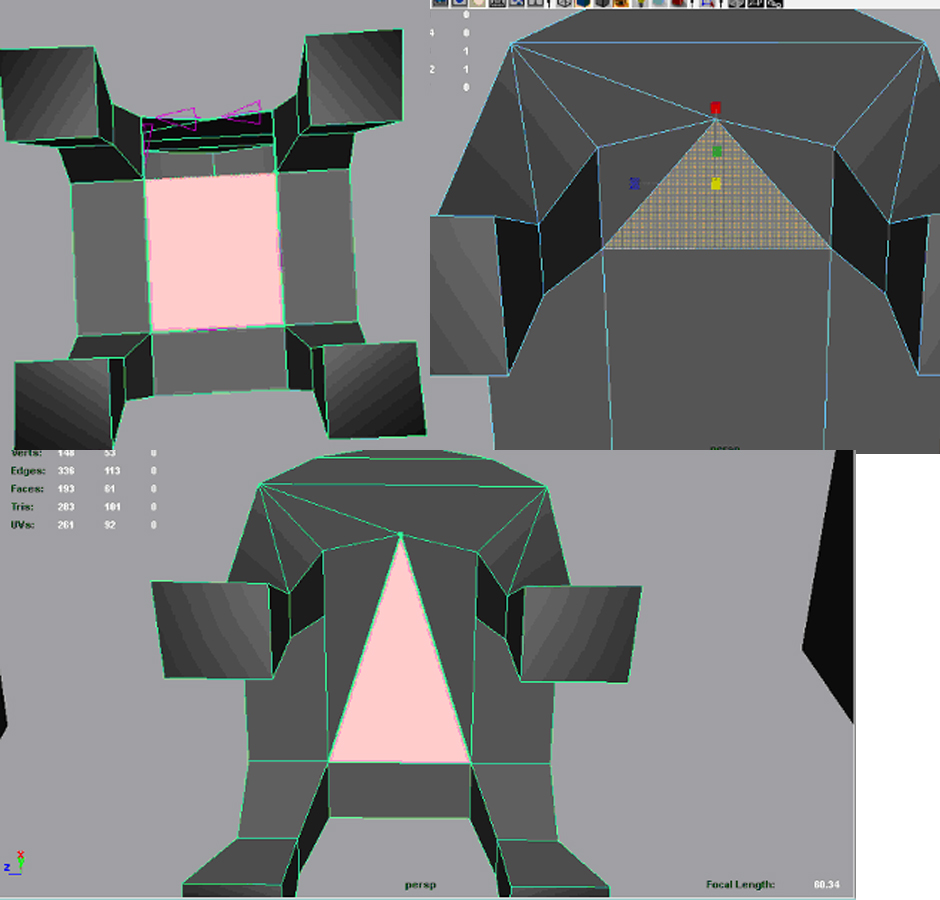
 7. Back to square one. I began to make a low poly clock from scratch.
 
 8. I started to sculpt it from the x axis’s again but this time I am going to be really strict on how many tri’s I’m using.

9. I used the add divisions tool to change the bottom face to 4. (There are quite a few ways to create the legs.)

10. After extruding the legs I selected the inner vertex’s and tried to scale them equally (It doesn’t matter if you’re slightly out because later I’m going to cut it into quarters). On different axis I lined them up with the x and z drawing guidelines.
 
11.  Now that I have finished the base of the four legs the rest is easy. With this I kept on extruding the legs and following the axis’s guidelines. 
 
12. With the extruded legs I selected the four vertex’s around the sides to be the tip of the feet. At this point I checked if to see the expanding points were in line with the x and z axis and to see if it’s scaled right.  

13.  Now is the time to concentrate on one leg of the clock and get it just right. I did this by scaling both sides of the vertex’s on one leg. As long as it looks right its fine as the only thing that this might effect is the UV mapping which I am going to do later.

14. This is when I added lines to cut out a quarter of the shape. I would only cut it if each side is symmetrical to each other. (So if I modelled a couch I could only put it in half but it all depends on the design and if it’s symmetrical or not)

 15. When I was happy with the leg I used the duplicate special tool to duplicate the leg parallel to the original. I then merged the two quarters to from a half and then delete the merge line.
 
16. I then used the duplicate special again for the half to be formed into a whole. I then merged the two sides. (138 tris)

17. Time to reduce as much of the unwanted tris as I can. I first removed the centre merge line and from there I joined it to the side, making sure it doesn’t make a 5 sided face. I then looked carefully in triangle to see if there is anymore I can reduce. I reduced the legs by connecting them to the start of the arch. I had to be very careful because I had to still retain the shape of the clock.
18. I finished the clock shape at 114 tris. But just to make sure I used the Clean up tool and made it highlight all the mistakes. There were no mistakes. ( :O slightly shocked at this but it is a simple design >.> if it was a higher poly, there would be more mistakes)

 19. The final touches was to go and highlight the edges and use the soften edge tool in the normal menu but I had to leave the extra edges of the clock stuck on hard edges. If I would have softened all the edge it wouldn’t have looked right.
(Next is reducing the polygon count)